Selecting an 800a Automatic Transfer Switch is not a simple matter of choosing the largest available cabinet. It is a reliability decision. The switch must handle heavy current, transfer safely, and support the facility’s actual emergency-power strategy. A hospital, data center, factory, and commercial building will not face the same operating conditions.
Electrical engineer and power-systems specialist Robert W. Smeaton wrote, “Reliability is the ability of a system to perform its intended function when required.” That principle fits an 800A Automatic Transfer Switch precisely. The device may remain quiet for months, then carry a critical load within seconds during a utility failure. Small details matter. Think about short-circuit ratings, bypass isolation, controller settings, enclosure heat, maintenance access, and generator compatibility. A loose connection or poorly tested sensor can create a serious failure.
This guide presents seven practical tips for evaluating an 800A Automatic Transfer Switch. It considers continuous current, switching mechanisms, protection coordination, installation space, monitoring, certifications, and lifecycle support. Some buyers focus too heavily on the nameplate rating. That is understandable, but incomplete. An 800A rating does not automatically guarantee suitable performance under every fault or environmental condition. I have also seen specifications that looked perfect until technicians discovered limited cable-bending space. The lesson is uncomfortable: paper compliance is not field readiness. Careful verification, realistic load data, and routine testing remain essential.
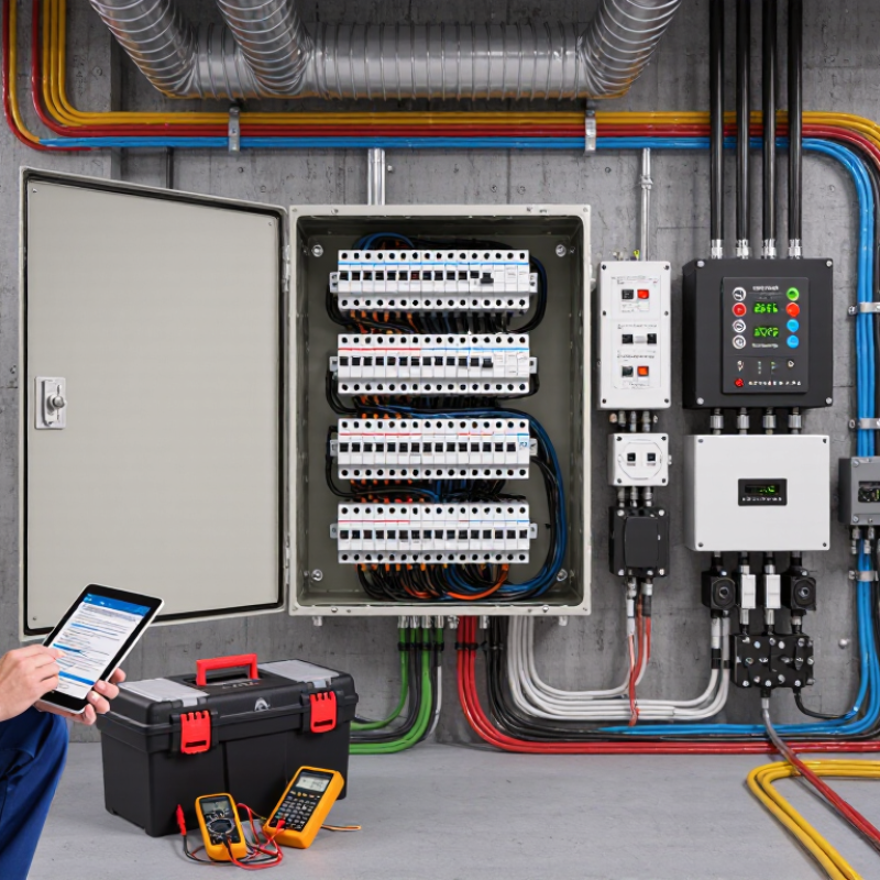
Choosing an 800A automatic transfer switch starts with defining the real load, not copying the main breaker rating. Record the system voltage, phase arrangement, frequency, number of poles, and available fault current. Then list every connected load, including motors, pumps, HVAC equipment, lighting, and control systems. Measure normal demand during peak operation. A quiet afternoon can hide the worst case.
Separate continuous loads from intermittent loads. Include motor starting current, transformer inrush, and any equipment that starts automatically. An 800A switch may carry the running load but still fail to transfer it smoothly when several motors start together. Check the generator’s usable output in kilowatts and kilovolt-amperes. The generator must support both steady demand and starting surges.
Transfer capacity also depends on the switch’s rated voltage, frequency, withstand rating, and switching duty. Confirm whether the application requires delayed transfer, closed transition, or neutral switching. These choices affect safety and system behavior. A neat spreadsheet can still lie. Field readings, updated load schedules, and manufacturer-tested performance provide stronger evidence. Have a qualified electrical professional verify calculations against local electrical requirements and the installation environment. Consider future expansion, but avoid excessive oversizing, which can reduce practical operating efficiency and raise project costs. After installation, test source failure, generator startup, transfer timing, retransfer, and manual operation under controlled conditions. Small omissions matter.

Comparison of calculated operating current, 125% design current, and an 800A transfer capacity at 480V, three-phase power.
The design current is based on the calculated three-phase current with a 125% allowance for continuous loads. The 800A transfer capacity provides sufficient margin for these example load profiles, but motor starting current, future expansion, short-circuit ratings, and local electrical codes must also be verified before selection.
Tip 1: Confirm voltage before reviewing enclosure size or accessories. An 800A automatic transfer switch must match the system’s nominal voltage and insulation rating. A 480V switch cannot replace a 208V model. The U.S. Energy Information Administration’s Electric Power Annual identifies 60 Hz service as standard across most U.S. commercial power systems. However, frequency alone does not confirm compatibility. Check the utility supply, generator output, neutral arrangement, and allowable voltage variation.
Tip 2: Match the phase configuration precisely. Single-phase, three-phase three-wire, and three-phase four-wire systems require different switching arrangements. Confirm whether the load needs a switched neutral. Inspect the one-line diagram, not just the equipment schedule. IEC 60947-6-1 addresses transfer switching equipment ratings and performance. It supports a disciplined review of current, voltage, frequency, and switching duty. Small drawing errors can create large commissioning problems.
Tip 3: Verify system behavior under real conditions. NFPA 110 specifies performance expectations for emergency and standby power systems, including transfer operation and source monitoring. Test the switch with both sources available, then simulate undervoltage and phase loss. Watch the controller, neutral connection, and generator response. The Uptime Institute’s Annual Outage Analysis repeatedly identifies power-related failures as major outage contributors. A final caution: engineers sometimes trust labels too quickly. Record measured voltage and phase rotation during commissioning, because documentation can be outdated.
7 Tips for Choosing an 800A Automatic Transfer Switch
Evaluate the switching mechanism before comparing enclosure size or price. Open-transition designs break the normal source before connecting the emergency source. They are simple, reliable, and often suitable for general commercial loads. Closed-transition designs briefly parallel both sources, reducing interruption. They require precise synchronization and careful utility coordination. Delayed-transition models pause between sources, helping discharge motors and prevent unwanted inrush. That pause can feel long in a control room.
Transfer performance must match the load profile. Check sensing accuracy, transfer time, retransfer time, and current withstand ratings. An 800A switch should be tested with realistic inductive loads, not only a clean resistive load bank. Watch the generator voltage recovery after motor starting. Small timing errors can become large disturbances. The National Fire Protection Association’s NFPA 110 standard emphasizes reliable emergency power transfer and periodic operational testing. IEC 60947-6-1 also provides requirements for transfer switching equipment.
Uptime Institute’s 2024 Annual Outage Analysis reported that 54% of respondents experienced an outage costing more than $100,000. That figure makes maintenance access and event records practical selection criteria. Choose adjustable time delays, visible position indication, and logged transfer attempts. Verify neutral switching requirements with the electrical engineer. Field commissioning should record source voltage, frequency, pickup points, and actual transfer time. I would not accept factory data alone. Real site conditions often expose weak assumptions.
| Tip | Evaluation Dimension | Practical Selection Criteria for an 800A ATS | What to Verify in the Datasheet or Test Report |
|---|---|---|---|
| 1 | Continuous current rating | Select an ATS with a continuous current rating of at least 800 A at the actual system voltage, frequency, ambient temperature, enclosure type, and installation conditions. Do not treat the frame size alone as the usable rating. | Confirm the rated operational current, rated insulation voltage, temperature-rise limits, conductor arrangement, and any derating requirements. The upstream and downstream protection must also be coordinated with the 800 A rating. |
| 2 | Switching mechanism | Compare mechanically held and electrically held mechanisms. Mechanically held designs generally maintain contact position without continuous coil power, while electrically held designs may require continuous control power to remain in position. | Check the mechanism type, motor or solenoid duty cycle, manual operating method, emergency operation, mechanical interlocking, and the number of operations covered by the endurance rating. |
| 3 | Open, closed, or delayed transition | Use open transition when the sources must never be paralleled. Consider closed transition only when the utility, generator, protection system, and local regulations permit momentary source paralleling. Use delayed transition where residual voltage decay or motor load characteristics require a controlled neutral position. | Verify the transition sequence, source interlocks, synchronization requirements, adjustable neutral delay, in-phase monitoring, and whether the design prevents unintended paralleling. |
| 4 | Transfer and retransfer performance | Evaluate sensing-to-transfer behavior rather than relying on a single advertised transfer-time figure. Transfer time depends on source qualification, engine-start delay, contactor or breaker movement, control settings, and load conditions. | Confirm adjustable undervoltage and underfrequency pickup thresholds, time delays, engine-start contacts, source-available logic, retransfer delay, and measured switching time under representative conditions. |
| 5 | Short-circuit withstand and closing performance | Match the ATS short-circuit withstand and closing rating to the available fault current at the installation point. An 800 A continuous rating does not by itself define the fault-current capability. | Review the tested short-circuit current rating or conditional short-circuit rating, test duration, protective-device requirements, system voltage, and whether the rating applies to the complete ATS assembly. |
| 6 | Phase, neutral, and sensing configuration | Select the correct system configuration: three-phase or single-phase, three-pole or four-pole switching, solid or switched neutral, and the required voltage-sensing arrangement. A switched neutral may be necessary where separately derived sources require isolation of the neutral conductor. | Confirm pole configuration, neutral ampacity, phase-loss and phase-sequence detection, voltage and frequency sensing range, generator warm-up logic, and compatibility with the grounding and bonding design. |
| 7 | Standards, maintenance, and monitoring | Choose equipment evaluated to the applicable requirements, such as UL 1008 or IEC 60947-6-1, and provide clear access for inspection, testing, and service. For critical loads, include remote status and event indication. | Verify certification for the intended market, routine test procedures, inspection intervals, replaceable control components, auxiliary contacts, alarm outputs, communication options, maintenance bypass provisions, and documented factory test results. |
Note: Final selection must be based on the system voltage, available fault current, grounding method, load characteristics, local electrical codes, and the requirements of the project engineer or authority having jurisdiction.
Tip 1: Check the safety features before comparing prices. An 800A automatic transfer switch handles serious current and needs strong mechanical and electrical interlocks. These controls should prevent both power sources from connecting at once. Look for short-circuit withstand ratings, visible position indicators, emergency manual operation, and adjustable time delays. Small details matter. During site inspections, unclear status markings often create avoidable maintenance errors.
Tip 2: Verify certifications through traceable documents, not sales claims. The switch should meet recognized standards required in your installation region, such as applicable UL or IEC requirements. Request current certificates, routine test records, and ratings for the complete assembly. A component may be certified while the final transfer switch configuration is not. That distinction is easy to miss. I have seen technically strong equipment delayed because documentation was incomplete.
Tip 3: Match enclosure protection to the actual environment. Dust, moisture, heat, and corrosive air can shorten service life quickly. Select an appropriate NEMA or IP rating, then confirm cable-entry methods and ventilation details. Outdoor installations may need UV-resistant materials, drainage, and protection from direct rain. Indoor rooms still require care. A clean electrical room today may become dusty after construction.
Reviewing the installation drawings with a qualified electrical professional is wise. Yet even experienced teams can overlook access clearance or maintenance space. Leave room for inspection, testing, and safe manual transfer. Reliability depends on both the switch and the conditions around it.
An 800A automatic transfer switch demands more than a basic load calculation. Confirm continuous current, fault withstand, available short-circuit current, and generator compatibility. IEC 60947-6-1 provides a useful framework for transfer-switch performance and testing. Cable bending space also matters. Space matters. Large conductors can turn a simple installation into a costly redesign.
Compare bypass isolation, neutral switching, enclosure rating, and access for infrared inspection. NFPA 70B emphasizes documented electrical maintenance and condition-based inspection. That supports easier service planning, especially where shutdowns are difficult. Field reviews often find that control wiring lacks clear labels. Small details create delays. Check ventilation, ambient temperature, and upstream protection before selecting the cabinet.
Long-term value includes testing labor, spare parts, monitoring, and downtime exposure. The Uptime Institute’s 2024 Annual Outage Analysis reported that 54% of serious outages caused at least 100,000 dollars in losses. An inexpensive switch may therefore carry an expensive risk. Still, oversized equipment is not automatically better; it can increase installation cost and reduce practical efficiency. Review actual demand, future expansion, and maintenance access with qualified electrical personnel. A careful choice can remain useful for years, although even careful forecasts deserve another review.

Cepex is the brand for the fluid handling market belonging to the Fluidra group. One of the leading european manufacturer of valves and fittings in thermoplastic materials.
Dedicated to the swimming pool, irrigation and industrial markets, we distribute our products worldwide with the Fluidra commercial network and presence in 46 countries with 136 sales branches.